产品
FIB-SEM
Nanomanipulators
OmniProbeOmniProbe Cryo软件
AZtec3DAZtecFeatureAZtec LayerProbeTEM
Hardware
EDSUltim MaxXploreImaging
软件
AZtecTEM
 牛津仪器集团成员

8th October 2019 | Author: Dr John Lindsay
To deliver the best sample quality during FIB lift-out it is increasingly common to rotate the lamella in order to optimise milling direction, a process described in my previous blog. Standard recipes combining both rotation of the OmniProbe and microscope stage have been calculated for common lamella re-orientations, such as plane view (rotate the lamella by 90o) and backside thinning (rotate the lamella by 180o). While these standard recipes are straightforward to execute it can still be a challenge to develop a workflow to do something less common.
One recent example we encountered was preparation of samples for in situ TEM experiments, in this case using a heating chip. Traditionally these experiments would be limited to samples such as nanoparticles which can be deposited onto a membrane layer (as seen in our recent blog on high temperature EDS). Through using the full capability of a nanomanipulator it is possible to prepare samples from bulk materials for test on these chips. This has been achieved by placing a FIB lift-out lamella on the chip ‘nearly flat’ (near plane view orientation), but at a slight angle.
If the lift-out lamella was placed flat (plane) it would be impossible to thin both sides as the heating chip itself would block the FIB, but by placing at a slight angle the FIB can be used to thin the sample after attaching to the chip. An example of this orientation as placed on a heating chip can be seen below.
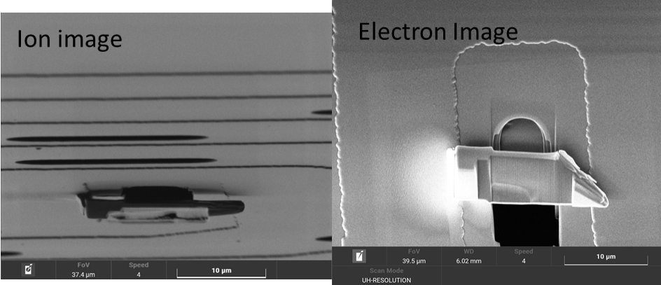
Fig. 1 Example of a bulk sample lifted out on to a heating chip, left image shows the FIB image of a lamella, both sides of the lamella are visible which means it can be thinned. Right is the electron image of the lamella, after both surfaces have been milled while attached to the chip.
In order to produce this sample both stage and probe rotations were calculated. The required stage and probe movements depend on the angle between the probe z-axis and the sample plane, the angle between the FIB column and the sample plane and the angle between the FIB column and probe port. As a result, but once calculated they provide a reliable and repeatable workflow.
The workflow used for this sample is shown below. One quirk of this workflow was the undercut, as when the sample is rotated it is easily visible. The obscured undercut is not an issue since the linear motion of the Omniprobe means the lift-out can be performed reliably with a single click. For anyone who has used an old system, this does feel strange, but it works.
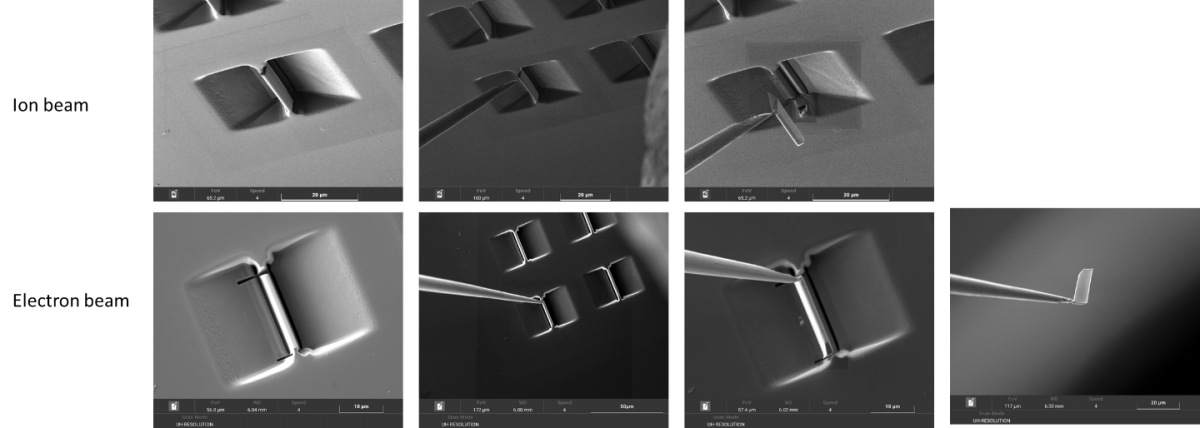
Fig. 2 FIB and electron images showing a bulk lift-out for a heating chip
With the ability to rotate both the stage and probe almost any orientation is possible (stage tilt and pre-tilts enable even more orientations). The first time attempting any new geometry lamella preparation is a challenge so when developing new workflows. and can be performed as easily and fast as a standard lift-out. Workflows for common geometries such as planar view and backside have been developed and published, meaning these advanced lift outs are now a routine.
To gain a better understanding of these workflows, or for advice on creating new ones, please contact one of our application experts.
Discover MoreWe send out monthly newsletters keeping you up to date with our latest developments such as webinars, new application notes and product updates.

© 牛津仪器 2026
 公安机关备案号31010402003473