产品
FIB-SEM
Nanomanipulators
OmniProbeOmniProbe Cryo软件
AZtec3DAZtecFeatureAZtec LayerProbeTEM
Hardware
EDSUltim MaxXploreImaging
软件
AZtecTEM
 牛津仪器集团成员
29th April 2020 | Author: Dr Sam Marks
After the challenge of spending approximately 4 to 36 hours preparing the perfect TEM sample, the acquisition of some great EDS data is often seen as the “easy bit”. So it’s highly frustrating when your perfect sample is providing far from perfect EDS results. These often manifest as lower than expected count rates and erroneous X-ray peaks.
In this blog, I will outline some of the key things to consider when preparing, mounting and analysing TEM samples. Today I have focussed on:
Following this advice should help reduce spurious peaks in your EDS spectra and improve the count rate of your system.
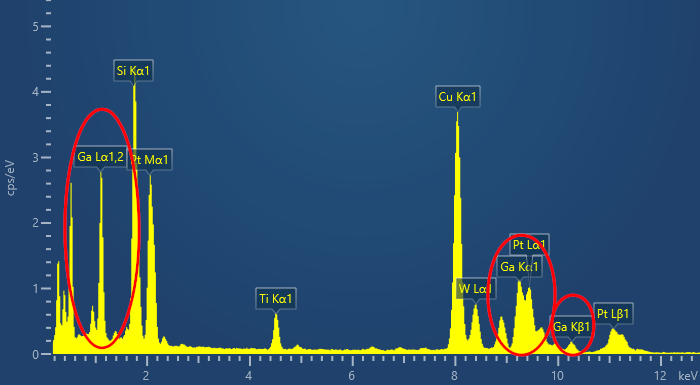
Poor sample preparation can result in large quantities of Ga within your EDS Spectrum. AZtec is capable of deconvoluting the Ga signal but this may result in an incorrect quantification result for extremely complex samples like semiconductors.
FIBs use heavy ions, typically gallium, which, when used at high accelerating voltages embed on the surface of your TEM sample resulting in unwanted Ga X-rays. This is inevitable during FIB sample preparation, but a lot can be done in the final steps of thinning to remove the embedded material and improve your EDS results. To remove the embedded Ga, users must ensure that they perform a range of low kV cleaning steps to finalise their sample preparation. Beam conditions will vary depending on your sample, but I recommend using an ion beam accelerating voltage of 5 kV and a small tilt angle of ± 5 - 7°. You then image the sample for 2/3 minutes on each side. By imaging the sample, instead of using a milling routine, you remain in control and can watch for any beam damage. Repeat the process at 2 kV for optimum results. An alternative to this, which applies not only to FIB but to conventional samples, is to utilise an ion polishing system to perform the low kV cleaning step.
Some tips and tricks on preparing a good FIB sample can be found here: Omniprobe Tech Tips: 3 steps to optimise FIB lamella quality
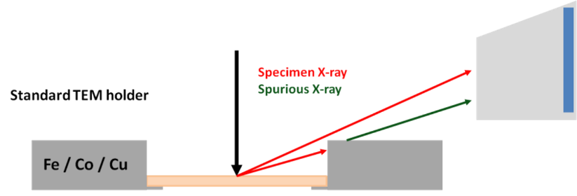
Standard TEM sample holders are built to be robust and easy to use. Unfortunately, this design is not optimised for EDS acquisition and often results in spurious X-rays being detected by the EDS detector.
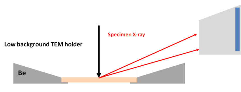
The choice of sample holder can be key in both removing spurious X-rays from your spectra and improving the number of X-rays being detected from your sample. Standard TEM sample holders are comprised of a deep trough to hold the sample and made from a steel alloy. EDS analysis using this holder can result in a reduction in input count rate (ICR) as X-rays will be blocked by the edges of the sample holder. It also results in spurious X-rays being generated by the holder material, this often manifests as Fe, Co and Cr in the EDS spectrum. These issues can be removed through the use of a low background EDS holder. These dedicated holders are built with components made from beryllium, a low atomic number element, removing spurious X-ray generation. As shown below the sample holder has refined edges to promote a clear line of sight between the sample and the detector.
The input count rate (ICR) is a measurement of the number of X-rays being detected each second by the EDS detector. The greater the number, the less time required to acquire your data. The primary method for increasing ICR is to use a broader spot size. By increasing the spot size you increase the beam current and produce more X-rays, the drawback being a reduction in image resolution. The loss of resolution can easily be overestimated, with TEM users conditioned to believe that spot 3 is only used for imaging and spot 8 must be selected for EDS acquisition. The truth is that all of the spots can be used for both and users should experiment with how much resolution loss they can accept to push up their ICR.
The quickest way to boost ICR is to tilt your sample ≈ 20° towards your EDS detector. Highlighted in the animation below, this will improve the geometry of your system and target more of the X-rays towards the detector. Unfortunately, this will have no effect on a dual detector configuration, as the boost in detector 1 will be observed as a decrease in detector 2.
Animation highlighting the effect of tilting your sample towards the EDS detector. As the stage is tilted towards the detector more of the detector is exposed to X-rays resulting in a greater input count rate.
I hope these tips and tricks help you to get more out of your EDS system, stay tuned for more updates in the future. If you’re feeling impatient, we recently released a webinar focussing on the latest developments in EDS hardware and software technology for the TEM, watch now to find out if you’re maximising your investment.
We send out monthly newsletters keeping you up to date with our latest developments such as webinars, new application notes and product updates.
© 牛津仪器 2024
 公安机关备案号31010402003473